Control-Plane Failure Patterns in Tool-Using LLM Systems
What this page is: an audit-oriented model and test checklist for multi-step, tool-using LLM systems.
What this page is not: a claim about any specific vendor trace or internal architecture.
Executive summary
This article defines two control-plane failure patterns that recur in audits of multi-step, tool-using LLM systems:
| Pattern | Failure mode | Typical impact | Minimum bar (“good”) |
|---|---|---|---|
| 1) Privilege persistence across interaction boundaries | Authorization context is treated as carryover state instead of being re-validated per tool call | Cross-thread/tab/conversation privilege bleed; writes in the wrong boundary | Per-call authorization + server-side enforcement; credentials bound + scoped + short-lived |
| 2) Non-enforcing integrity signals | Integrity risk is detected but execution state does not change (“detect without enforcement”) | Tainted artifacts continue to influence routing/tools across steps | High-risk signals trigger enforcement actions (hold/deny/quarantine) + circuit breakers |
Evidence boundary: the patterns are vendor-agnostic; the references are standards/guidance used to define terms and testable controls.
Scope and terminology
This article focuses on control-plane failures in systems where an LLM participates in a multi-step controller loop and can invoke tools/connectors.
System model (terminology used here)
- Control plane: the policy and orchestration layer that decides what may happen and enforces it: identity/session binding, context construction, routing/selection, tool authorization, integrity checks, and enforcement actions.
- Data plane: the side effects produced by tools/connectors (API calls, writes, state changes).
This aligns with the control-plane/data-plane framing used in Zero Trust architecture discussions. :contentReference[oaicite:0]{index=0}
PDP vs PEP (decision vs enforcement)
- Policy decision point (PDP): the component(s) that decide allow/deny for a proposed step/action.
- Policy enforcement point (PEP): the component that enforces allow/deny before any side effect (tool execution).
(See NIST SP 800-207; also reflected in ZTA diagrams and component definitions.) :contentReference[oaicite:1]{index=1}
Principle anchors (security engineering)
- Complete mediation: every access must be checked for authority.
- Fail-safe defaults: default deny unless explicitly permitted.
(These principles are attributed in the Saltzer & Schroeder design-principles literature.) :contentReference[oaicite:2]{index=2}
Interaction boundary (terminology used here)
An interaction boundary is a user-visible separation such as thread/tab/conversation/workspace.
A UI boundary is not a security boundary unless the backend and tool gateway treat it as a boundary for authorization and state.
Integrity signal (terminology used here)
An integrity signal is any detection output that indicates a risk of tainted inputs/state (e.g., poisoned retrieval, suspicious tool output, policy-violating arguments).
A signal is only useful for preventing harm if it can change execution state (hold/deny/quarantine).
Concrete schematic (example)
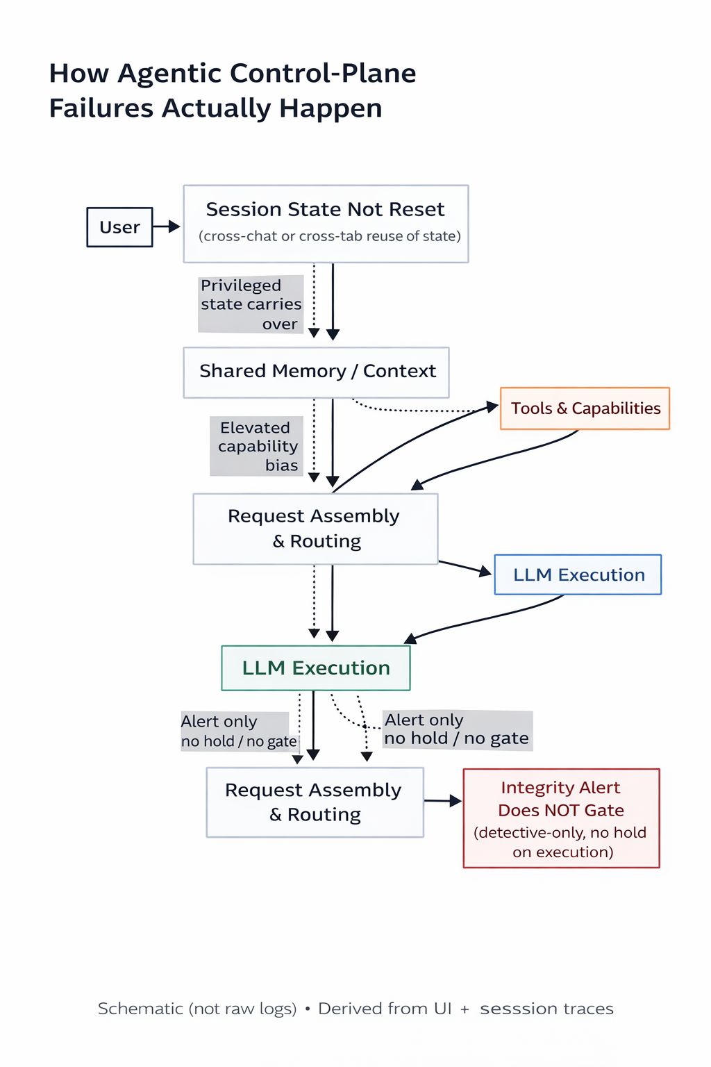
Pattern 1 — Privilege persistence across interaction boundaries
Definition (failure mode)
Privileged authorization context (identity binding, tool scopes, “write-capable” mode, or equivalent) persists across an interaction boundary because the system does not enforce a hard server-side boundary at the PDP/PEP layer.
Why it matters (testable impact)
If authorization becomes implicit carryover state, the system stops enforcing complete mediation at the moment it matters most: the next tool call.
That converts “allowed to write” from a per-call decision into cached context that can drift across steps and boundaries.
Common root causes (audit targets)
- A single tool/connector credential is reused across multiple boundaries without binding it to the subject and boundary (e.g.,
principal_id+conversation_id/thread_id). - An allow decision (“write-capable”) is cached without invalidation on boundary changes, privilege drops, or TTL expiry.
- Client/UI state is treated as authoritative for tool access rather than enforcing authorization at a server-side gateway/PEP.
Controls (minimum bar)
- Hard boundary on interaction switch: privileged modes reset on boundary change; write-capable operations require re-authorization in the target boundary.
- Bound, scoped, short-lived credentials: mint per principal (and per boundary when applicable), minimal scope (read vs write separated), short TTL.
- Per-call authorization (PDP → PEP): every tool invocation is authorized and enforced server-side before side effects.
- Least privilege by construction: minimize tool surface and default to read-only where feasible.
Authorized regression tests
1) Cross-boundary privilege bleed: authorize writes in Boundary A → switch to Boundary B → attempt a write.
Expected: deny/hold unless Boundary B re-authorizes.
2) Credential binding replay: replay a valid credential from Boundary A in Boundary B.
Expected: deny (binding mismatch).
3) Authority change mid-session: revoke role/scope → repeat the same write.
Expected: deny on the next call (no stale authorization).
Pattern 2 — Non-enforcing integrity signals
Definition (failure mode)
The system detects integrity risk (tainted context, anomalous memory, suspicious tool output, policy-violating arguments) but continues execution (“alert only”), allowing flagged artifacts to re-enter context and influence later steps.
Why it matters (testable impact)
In multi-step controller loops, contaminated artifacts can influence:
- routing/tool selection,
- argument construction,
- subsequent LLM steps.
A monitoring-only signal does not reduce the likelihood of side effects if execution proceeds unchanged.
Common root causes (audit targets)
- Integrity checks run after tool selection or argument construction (too late in the lifecycle).
- Alerts exist but there is no execution-state transition (no hold/quarantine/deny path).
- No circuit breaker: repeated integrity signals still allow retries, increasing exposure.
Controls (minimum bar)
- Fail-safe defaults for high-risk signals: prefer hold/deny over “continue”; require explicit approval to resume.
- Quarantine tainted artifacts: flagged memory/retrieval/tool outputs are prevented from re-entering context until reviewed/replaced.
- Circuit breakers: repeated integrity violations stop execution or degrade to read-only; write intent requires operator approval.
- Pre-execution validation: validate tool selection + arguments (schema + semantic constraints) before side effects (PEP pre-execution).
Authorized regression tests
1) Poisoned-input enforcement: inject an untrusted chunk that triggers an integrity rule.
Expected: step is held/blocked and artifact is quarantined.
2) Policy-violating arguments: craft model output that violates a scope/tenant/resource constraint.
Expected: rejected by the PEP before tool execution.
3) Repeated-signal circuit breaker: trigger the same integrity signal N times.
Expected: execution stops or degrades to read-only.
Test matrix (copy/paste)
| Pattern | Test | Expected enforcement point | Expected result |
|---|---|---|---|
| 1 | Cross-boundary privilege bleed | PEP (server-side) | Deny/hold unless boundary re-authorizes |
| 1 | Credential binding replay | PEP (server-side) | Deny on binding mismatch |
| 1 | Authority change mid-session | PDP+PEP on next call | Deny on next invocation |
| 2 | Poisoned input triggers rule | Controller enforcement / PEP | Hold/deny + quarantine artifact |
| 2 | Policy-violating args | PEP pre-execution | Reject before side effect |
| 2 | Repeated integrity signals | Circuit breaker | Stop or degrade to read-only |
Minimal audit checklist (copy/paste)
- Is privileged context invalidated on interaction boundary change (and via TTL)?
- Are credentials scoped to least privilege and bound to the right subject (and boundary where applicable)?
- Is every tool call authorized per call (PDP) and enforced pre-side-effect (PEP), not inferred from UI/session carryover?
- Do integrity signals change execution state for high-risk cases (hold/deny/quarantine), rather than only alert?
- Is there a circuit breaker for repeated integrity violations (stop / degrade / require approval)?
- Are tool arguments validated (schema + semantic constraints) before any side effect?
References
- OWASP Cheat Sheet Series — AI Agent Security Cheat Sheet: https://cheatsheetseries.owasp.org/cheatsheets/AI_Agent_Security_Cheat_Sheet.html
- OWASP — Securing Agentic Applications Guide 1.0: https://genai.owasp.org/resource/securing-agentic-applications-guide-1-0/
- OWASP — Top 10 for LLM Applications (2025): https://genai.owasp.org/llm-top-10/
- NIST SP 800-207 — Zero Trust Architecture (PDP/PEP; PE/PA; control plane vs data plane): https://doi.org/10.6028/NIST.SP.800-207
- NIST SP 800-53 Rev. 5 — Security and Privacy Controls: https://doi.org/10.6028/NIST.SP.800-53r5
- Saltzer & Schroeder (1975) — The Protection of Information in Computer Systems: https://www.cl.cam.ac.uk/teaching/1011/R01/75-protection.pdf
Suggested reading
- Orchestration risk (controller loop): The Attack Surface Isn’t the LLM — It’s the Controller Loop
- Request construction checkpoints: Request assembly threat model: reading the diagram
- Trust boundary audit checklist: Agentic Systems: 8 Trust-Boundary Audit Checkpoints
- Procedure (enforcement gate): Engineering Quality Gate — Procedure